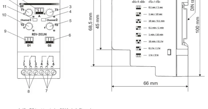
TWO CHANNEL MULTIFUNCTION TIME DELAY REV-201M

REV-201M is designed for the commutation of electrical circuits of 240V 50Hz AC as well as 24V DC electrical circuits with the adjustable time delay setting.

The relay has two channels and can be operated by one of seven operation algorithms that the user specifies:

– Turn ON time delay relay;

– Pulse relay 1;

– Intermittent (cyclic) relay 1;

– Operation relay (star-delta);

– Pulse relay 2;

– Intermittent relay 2;

– OFF delay relay.

REV-201M could be used as the relay of pre-starting signalization for the machinery that require to announce that some mechanism or machinery will soon take a start to make people aware of this and get away from the risky zones. Widely used for steel plants, heavy machinery, cranes and construction mechanisms as well as mining companies for the technological stuff safety.

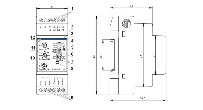
THREE PHASE VOLTAGE MONITORING RELAY RNPP-311M

RNPP-311M voltage monitoring relay is designed for protection of three phase loads against major types of mains faults, such as:

  • RMS voltage reaching beyond admissible thresholds – over and under voltage
  • Phase loss or Single phasing
  • Phase sequence order violation or reverse phase sequence
  • Phase coincidence or shorting of two or more phases
  • Phase Imbalance or asymmetry

The device performs monitoring of the main circuit parameters and de-energizes (trip) load when the parameters fall beyond specified boundaries.

The front panel LEDs display the following:

  • Presence of true RMS voltage in the mains
  • Load status (On/Off)
  • Type of fault

Adjustment potentiometers allow for setting:

  • Tripping threshold for the minimum/the maximum voltage, (% of the rated voltage)
  • Time delay for load re-energizing (reset) after the circuit parameters recovery
  • Tripping time delay for load de-energizing (trip) in case of all circuit voltage faults

SINGLE PHASE VOLTAGE MONITORING RELAY RN-113

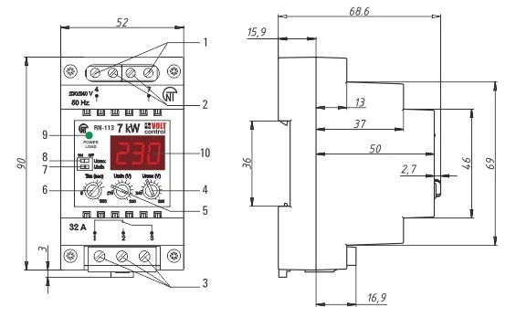
RN-113 single phase voltage monitoring relay is designed to de-energize an industrial/appliance single-phase 220V/50Hz load in case of inadmissible voltage variations in the mains with subsequent automatic re-energizing after the circuit parameters recovery. Load is connected to the relay either directly via relay terminals or through a magnetic starter, depending on the wattage.

The relay can operate in four independent modes:

  • Voltage monitoring relay
  • Minimum voltage monitoring relay
  • Maximum voltage monitoring relay
  • Time relay with a restart delay

The device front panel features load status indicator (on/off) and three-digit, seven-segment display, which displays (depending on the device status):

  • Actual RMS voltage
  • Accurate value of the set-up parameter
  • Time remaining till automatic load re-energizing
  • Emergency de-energizing the load (RMS voltage flashing)

SINGLE PHASE VOLTAGE MONITORING RELAY RN-111M

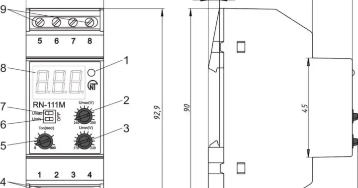
RN-111M single phase voltage monitoring relay is designed to de-energize an industrial/appliance single phase 220 – 240V/50Hz load in case of inadmissible voltage variations in the mains with subsequent automatic re-energizing after the circuit parameters recovery. Load is connected to the relay either directly via relay terminals or through a magnetic contactor, depending on the wattage.

The relay can operate in four independent modes:

  • Maximum and Minimum Voltage monitoring relay
  • Minimum voltage monitoring relay
  • Maximum voltage monitoring relay
  • Time relay with a restart delay

DIGITAL INPUT-OUTPUT MODULE FOR IOT SOLUTIONS OB-215

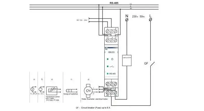
Digital I/O OB-215 can be used as the following:

− remote DC voltage trasducer input (0 – 10 V);

− remote DC current transducer input (0 – 20 mA);

− remote temperature meter with the ability to connect sensors NTC (10 KV), PTC 1000, PT 1000 or digital temperature sensor D18B20;

− temperature regulator for cooling and heating plants;

− pulse counter with saving the result in memory;

− pulse relay with switching current up to 8 A;

− interface converter for RS-485 – UART (TTL).

OB-215 provides:

− equipment control using relay output with switching capacity up to 1.84 kVA (8A);

− tracking the state (closed/open) of the contact at the dry contact input.

RS-485 interface provides control of the connected devices and reading of the sensors readings via the ModBus protocol.

Parameter setting is set by the user from the Control Panel using the ModBus RTU/ASCII protocol or any other program that allows working with the ModBus RTU / ASCII protocol.

The status of the relay output, the presence of the power supply and the data exchange are displayed using indicators located on the front panel

ОВ-215 allows data exchanging with external devices via the serial interface of RS (EIA/TIA)-485 via ModBus protocol with the limited set of commands (see Table 5 for a list of supported functions).

When constructing a network, the principle of the master-slave organization is used where OB-215 acts as the slave. There can be only one master node and several slave nodes in the network. As the master node is a personal computer or a programmable logic controller. With this organization, the initiator of the exchange cycles can only be the master node.

The queries of the master node are individual (addressed to a particular device). OB-215 performs transmission, responding to individual queries of the master node.

If errors are found in receiving queries, or if the received command cannot be executed, OB-215 as the respond generates an error message.

PROTOCOL CONVERTER (RS485 MODBUS TO ETHERNET) ET-485

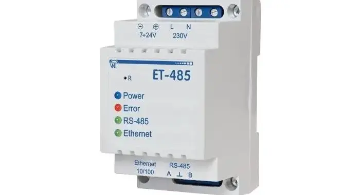
ET-485 is a microcontroller unit. It is designed to exchange data over the Ethernet 10BASE-T and 100BASE-T network using the equipment, which is provided with the RS-485 interface and establishing a Modbus network. The standard network mapping using the RS-485 is provided. The unit fulfills the functions of a ‘Modbus Server’ for switching the Modbus clients to the Ethernet network. It redirects the Modbus requests from the clients to the units in the Modbus network and returns their answers to the clients.

ET-485 has:

  • Flexible addressing within the Ethernet network (overloading MAC-address, static and dynamic IP- address)
  • Access protection over the Ethernet network (password for configuration mode, IP- address filter for setting and switching to the Modbus network)
  • Different data transfer modes for Modbus network (RTU and ASCII with/without odd-even check, wide range of transmission speeds, selectable delays)
  • Free PC software for programming/settings and monitoring

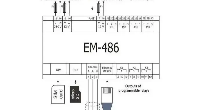
INTERFACE CONTROLLER FOR IOT WITH BUILT-IN I/Os EM-486

Interface controller with built-in I/Os for Remote Operation/Monitoring EM-486 provides access to readings of communicable devices, gauges and sensors from their registers of Modbus connected via RS-485 interface with the help of text SMS messages, automatic data gathering from the selected devices, transmitting the gathered data via GPRS or Ethernet to various SCADA interfaces, automatic transmitting SMS alarms of state of selected devices.

EM-486 has:

  • Flexible options of connection (via wire or wireless communication, automatic method selection of communicating with a server, automatic or manual selection of GSM provider and communication parameters, resetting of MAC-address and other Ethernet settings);
  • Protection of access (password for setting mode, filter of IP-address for setting or connection to Modbus network, connection only to the selected server with automatic log-in, password for control via SMS);
  • Different modes of data interchange via Modbus network (RTU or ASCII, with checking of parity for even-odds or without checking, wide range of transmitting rate, adjustable delay);
  • Programmable relay outputs for reaction at events and alarms;
  • Programmable inputs for sensors;
  • Power output for sensors;
  • Reserve power supply input;
  • Service functions (saving the collected data to flash memory card including the restoring of transmitting in case of communication break down, data single sourcing on the selected external server, software updating option).
  • EM-486 meets the requirements of IEC 60950-1:2001 Data processing devices.

EM-486 provides control for MODBUS devices in RS-485 network via Ethernet interfaces or GPRS, or via the SMS. The unit also allows to read data from devices by MODBUS or from connected sensors.

The processor supports connection to the accumulating data cloud server via Ethernet network with a help of micro chip of physical interface of Ethernet (or via GPRS with a help of inbuilt GSM-modem, if connection via Ethernet is not available).

In addition, EM-486 can be connected to Ethernet via MODBUS TCP Protocol to exchange data with MODBUS devices, or with the product. The controller receives and processes SMS with a password and command read/write for Modbus devices.

When inserting a memory card the product reads the internal memory for operational logic – program for data collection and tracking of events. The program runs in the background mode.

Product stores in the internal memory the network settings, parameters of inputs and outputs, the logic of action, the collected data log.

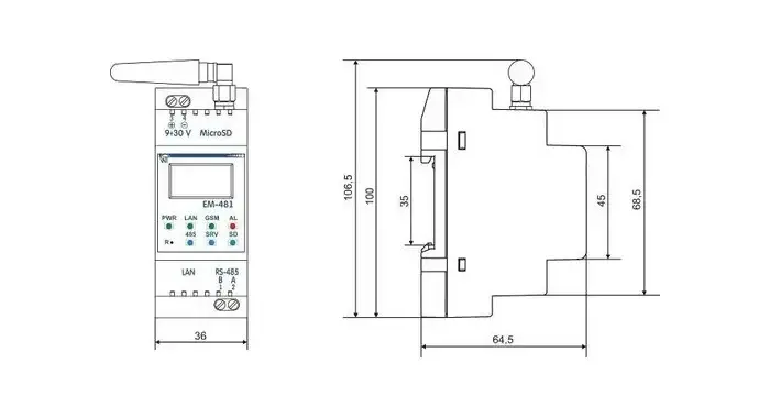
INTERFACE CONTROLLER FOR IOT SOLUTIONS EM-481

EM-481 provides data collection from connected MODBUS devices, data transfer to the server, data access via MODBUS TCP (GPRS, Ethernet) or SMS text messages (GSM), event tracking and response to events (sending SMS notifications, recording values to MODBUS devices).

EM-481 provides:

· Flexible options of connection (via wire or wireless communication, automatic method selection of communicating with a server, automatic or manual selection of GSM provider and communication parameters,

resetting of MAC-address and other Ethernet settings;

· Protection of access (password for setting mode, filter of IP-address for setting or connection to Modbus network, connection only to the selected server with automatic login, password for control via SMS);

· Different modes of data interchange via MODBUS network (RTU or ASCII, with checking of parity for even-odds or without checking, wide range of transmitting rate, adjustable delay);

· Programming the collection of data, events, and action for events (see Appendix С);

· Service functions (real time clock, firmware updating option).

The device provides control for MODBUS devices in RS-485 network via Ethernet interfaces or GPRS, or via SMS. The device also allows reading data of devices by MODBUS. The processor supports connection to cloud-based data collection server via Ethernet network with a help of microchip of physical interface of Ethernet (or via GPRS with a help of in-built GSM-modem, if connection via Ethernet is not available).

In addition, the device can be connected to Ethernet via MODBUS TCP Protocol to exchange data with MODBUS devices, or with EM-481. The controller receives and processes SMS with a password and command read/write for Modbus devices.

When inserting a memory card the device reads the internal memory for operational logic – program for data collection and tracking of events. The program runs in the background mode.

The device stores the network settings, safety parameters, the logic of action, the collected data log in the built-in memory.
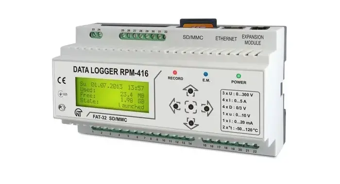
POWER QUALITY ANALYSER AND DATA LOGGER RPM-416

Power Analyser and Data logger RPM-416 is a device intended for power quality analysis, electrical & process parameters measuring, monitoring as well as data archiving/storage with a sampling rate starting from 1 millisecond.

– Data sampling rate 1 msec – 3600 sec.

– Data archiving is made on the removable memory card (SD/MMC), which can be later analyzed in free PC software program provided with the logger.

– RPM-416 has an inbuilt real time clock powered by internal lithium-type battery.

– Device can be connected to Ethernet network via standard 10Base-T or 100Base-T. Data transfer happens simultaneously with data recording to memory card.

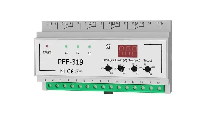
AUTOMATIC ELECTRONIC PHASE SELECTOR PEF-319

PEF-319 universal automatic electronic phase switching device is designed to supply an industrial and domestic single phase 220/230/240 V, 50 Hz load from three-phase four-wire mains 3×380+N in order to maintain uninterrupted power supply of essential single-phase loads and protect them against unallowable voltage variations in the mains. According to the voltage presence and voltage quality on the phases, the PEF-319 will automatically select the optimum phase in limits range set by user and switch the single phase load supply to this phase:- If power is less than 6.6 kW (30 A), the load is energized directly from the PEF-319;- if power is more than 6.6 kW (30 A), the PEF-319 controls the magnetic contactor (MC) single phase coils of the corresponding power (MC are not included in supply complete package). The maximum and minimum voltage limits are set by user adjusting the potentiometers on the front panel as per requirement.

The electronic phase switch PEF-319 is a microcontroller-based digital device. User should make setting of trip threshold limits of PEF-319 – the minimal and maximal voltage values at which PEF-319 trips and switches off the load (or switches over to another phase). Phase L1 has the highest priority. It means that at normal parameters of voltage on all phases connected to PEF-319 (L1>L2>L3), the load will always be energized from phase L1. If on L1 the value is out of limits set by user, PEF-319 switches the load to the nearest by priority phase in not more than 0.2 seconds if the its voltage corresponds to the normal level. If the voltage on the reserve phases does not correspond to the trip set limits the load switches off. After the load had been switched to another phase and the voltage parameters had been restored on the priority phase, the load will be switched back to the priority phase in return time r (from 5 to 200 sec, settable) set by user. If r is in the position “∞”, the return to the priority phase will be performed only when voltage on the other phase goes out of the threshold limits.

In case when the voltage supplied on load goes lower than the minimal threshold limit the load switching over or switching off should be performed with a time delay of 12 seconds. When the voltage goes higher than the maximal threshold limit or goes 30 V lower than the minimal threshold limit, the load switching over or switching off will be performed with time delay of 0.2 seconds. During the load switching off the PEF-319 continues to perform the voltage control on all phases. When the voltage normalizes within the limit range on one of the phases.