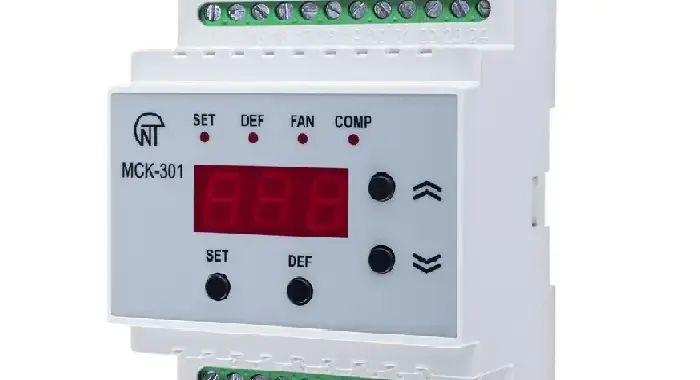
INTELLIGENT HVAC-ROOM TEMPERATURE CONTROLLER MCK-301-6X

MCK-301-61 controller for HVAC and room temperature devices is designed for:

  • indoor temperature monitoring;
  • climate devices control according to measurement data;
  • alarm signaling with a corresponding indication about user- specified maximum indoor temperature exceeding;
  • change of status between main and stand-by air conditioners after user-set time delay has expired;
  • switching to an operational air conditioner and signaling about a fault when one of the air conditioners is faulty;
  • all temperature devices are switched off when there is a fire alarm signal;
  • the average indoor temperature indication;
  • indication of the climate device that is in operation at the moment.

The controller provides the modes of operation as follows:

— connected electric heater thermostat conditions;

— air conditioning zone control thermostat conditions;

— alarm conditions;

— testing conditions.

DEMAND CONTROLLER OVERCURRENT-EARTH FAULT RELAY OM-310

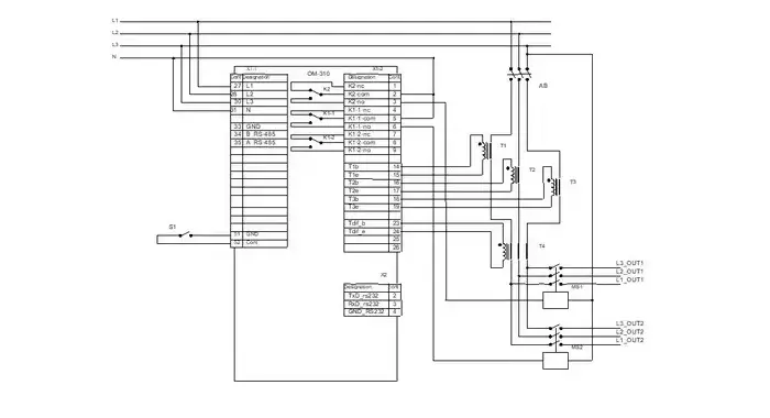
OM-310 Numeric Power Management System is used for:

  • Power Monitoring
  • Demand Controlling
  • Generator protection
  • Overcurrent protection
  • Earth leakage protection
  • Voltage monitoring
  • Complete load rejection when the power consumption exceeds the main threshold for a user-set time
  • Partial load rejection when the power consumption exceeds the main threshold for a user-set time
  • Measurement and indication of three-phase electric circut parameters (active values of phase and line voltages)
  • Positive, negative and zero phase sequence voltages; active phase current values; active, reactive and full power load consumption, power factor
  • Emergency signaling
  • Remote monitoring and load activation/deactivation via the RS-232/RS485 interface or external switch

The device allows working with a load of 2.5 – 30 kW with the use of integrated current transformers, and with a load of up to 450 kW with the use of external current transformers, including in networks with an insulated neutral.

THREE PHASE MOTOR PROTECTION DEVICE UBZ-302

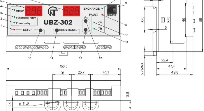
UBZ-302 has been designed for protection of asynchronous induction motors ranging from 2.5 kW to 30 kW that use of integrated current transformers and 30 kW to 315 kW through use of external current trnsformers, including in circuits with insulated neutral.

UBZ-302 provides for electric motor protection in case of:

  • poor quality supply voltage (unacceptable voltage surges, phase loss, incorrect phase sequence and phase coincidence, phase/line voltage imbalance);
  • mechanical overloads (symmetrical phase/line current overload);
  • exceeding the negative sequence current threshold;
  • phase current imbalance without overload, induced by the insulation fault inside the motor and/or the lead cable (the current imbalance factor is compared to the voltage imbalance factor using negative sequence);
  • loss of motor torque (“dry stroke” for pumps) – protection based on the minimal starting and/or operating current;
  • delayed motor start or rotor locking;
  • abnormally low insulation level between the fixed coil and frame (testing before motor startup);
  • ground fault of the stator coil during operation – protection against ground leakage current;
  • motor thermal overload;
  • coil overheating (measuring the coil temperature with integrated temperature sensors, or the body temperature with external temperature sensors).

For each protection type, automatic reclosing (ARC) can be enabled or disabled.

The device provides for electric equipment protection by means of controlling a magnetic starter (contactor) coil.

The device detects the presence of load currents when the load relay is open (when the load relay is open and the functional relay is in the star-delta mode). In this case the Unit initiates the alarm of external Magnetic Starter (further in text as MS), which starts the engine, until the unit or the control of engine currents are switched off while the load relay is deactivated.

UNIVERSAL THREE PHASE MOTOR PROTECTION RELAY UBZ-301

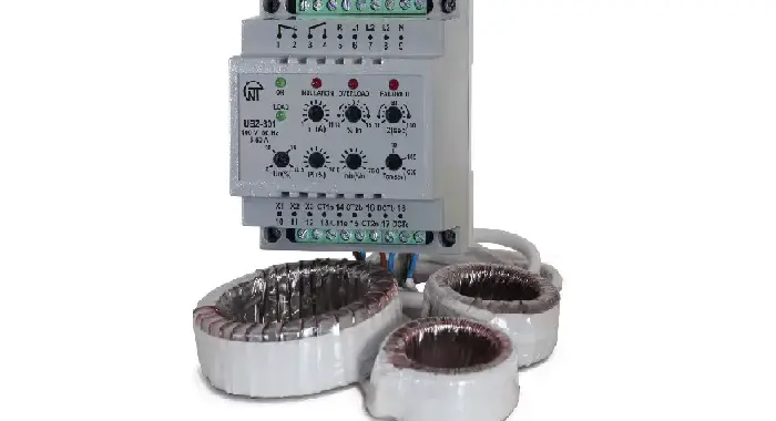
Universal Protection Devices For Asynchronous Electric Motor. UBZ-301 universal electric motor protection unit (further referred to as the unit) is designed for continuous monitoring of the circuit voltage parameters and phase/line RMS currents of three-phase 415V/50Hz AC electrical equipment, primarily, of induction asynchronous motors (EM) with wattage rating from 2.5kW up to 315 kW, as well as those with isolated neutral line. Three device versions are manufactured, with differentiation by current ratings: UBZ-301 5-50A, UBZ-301 10-100A and UBZ-301 63-630A The unit provides full and effective protection of electrical equipment by de-energizing and/or disabling its start in the following cases: when the mains voltage is of poor quality (unallowable voltage surges, phase loss, incorrect phase sequence and phase

THREE PHASE VOLTAGE & NEUTRAL MONITORING RELAY RNPP-312

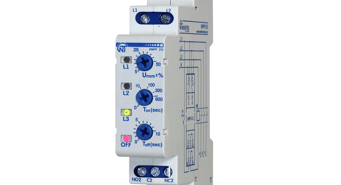
RNPP-312 has been designed:

  • for monitoring the permissible voltage level;
  • for monitoring the correct alternation and absence of sticking of phases;
  • for monitoring the full-phase and symmetry of the mains voltage (phase imbalance);
  • to disconnect the load in case of improper mains voltage and neutral failure;
  • for monitoring the quality of the mains voltage after switching off the load and automatically turning it on after restoring the voltage parameters;
  • to indicate the failure in the event of emergency situation and the presence of voltage in each phase.

The device provides the possibility of adjusting the parameters (voltage threshold, time of automatic reclosing and time delay of protection operation), selection of the voltage of the monitored mains (400 V or 415 V) and a set of protective functions. After restoring the voltage parameters of the mains, the device enables again the load after the reclosing time.

POWER CONTROLLER & CURRENT-VOLTAGE MONITORING RELAY OM-163

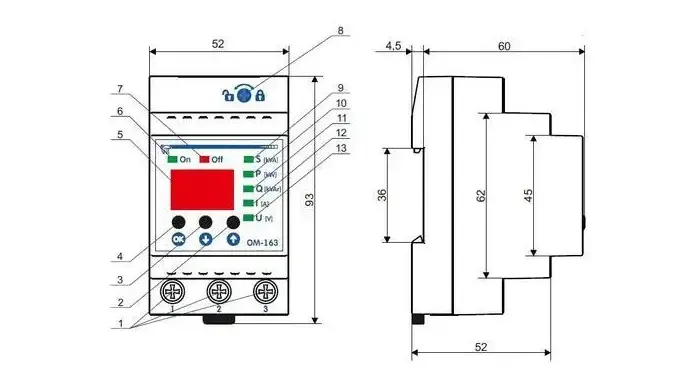
ОМ-163 is designed to protect (disconnect) the equipment (load) connected to it in the following cases:
− exceeding the threshold value of the controlled parameter;
− deviation of the mains voltage from the set values;
− excess of the temperature of the contact group (85 °С).

ОМ-163 can be used as:
− power consumption limiting relay;
− voltage relay;

— current overload relay;

− energy meter (indication of total, active, reactive power, current consumption and mains voltage).

ОМ-163 is powered by the circuit that feeds the load. ОМ-163 displays the value of the parameters and the status of the relay using LED indicators and display.

PROGRAMMABLE SEQUENTIAL AND COMBINATION TIMER TK-415

Sequential and Combination Timer with RS-232 communication

Basic functions:

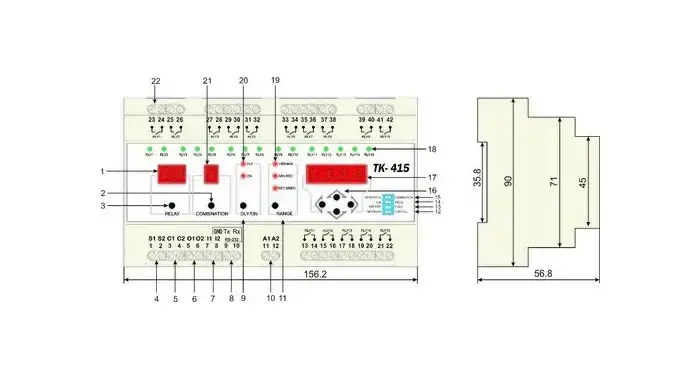
  • 15 channel (potential free relay outputs)
  • Microprocessor controlled
  • Selectable sequential and combination modes in one timer
  • Simple change-over between sequential and combination timer
  • 7-segment LED indications
  • Cascade connection of several devices for extended total number of channels
  • Memorization of program after switching off and program operation restart from breakage
  • Inputs for timer start and pause control
  • Fast resetting
  • Copy of settings
  • Selectable time range SEC:MSEC, MIN:SEC, HRS:MIN
  • RS-232 communication for programming and DCS integration (free PC software provided)
  • Program can be executed only one time or/and cyclic operation possible

Timer programming: 

Sequential Timer Programming:

  • Fix switch RUN/PROG in position PROG
  • For sequential timer selection fix switch SEQ/COMB in position SEQ. Supply power to inputs A1 and A2
  • Using the button RELAY select the channel 1
  • Using the button DLY/ON select time DLY for time setting, during which the contacts of channel relay will be open
  • Press RANGE for selection of necessary time range
  • Using arrow button to set the necessary time
  • Repeat steps 4 through 6 for status time setting ON, during which the contacts of channel relay will be closed
  • Repeat steps 3 through 7 for setting of other channels

Combination Timer Programming:

  • Fix switch RUN/PROG in position PROG
  • For selection of combination timer fix switch SEQ/COMB in position COMB. Energize the inputs A1 and A2
  • Using button RELAY select channel 1
  • Using button COMBINATION select combination 1
  • Using button DLY/ON select time DLY for time setting, during which the contacts of channel relay will be open
  • Press RANGE for selection of necessary time range
  • Using arrow buttons set the necessary time
  • Repeat steps 5 through 7 for set of status ON, during which contacts of channel relay will be closed
  • Repeat steps 4 through 8 for setting the other channel combinations
  • Repeat steps 3 through 9 for setting of other channels and their combinations

AUTOMATIC ELECTRONIC PHASE SELECTOR PEF-320

PEF-320 universal automatic electronic phase switch is designed to supply an industrial and domestic single phase 230 V, 50 Hz load from three-phase four-wire mains 3х400+N in order to maintain uninterrupted power supply of essential single-phase loads and protect them against unallowable voltage variations in the mains.
According to the voltage presence and voltage quality on the phases, the PEF-320 will automatically select the optimum phase in limits range set by user and switch the single phase load supply to this phase. It is possible to connect to one of the phases of the electric generator and inverter. The maximum and minimum voltage limits are set by user.

DRY TRANSFORMER TEMPERATURE CONTROLLER TR-100

ТR-100М is microprocessor based device intended to measure and control temperature mode of dry-type transformer with four transducers connected by two or three wire circuit, with subsequently displaying the temperature on the display and sending alarms when any parameters are outside preset limits.

The product can also be used for protection of HV motors and generators.

The product has universal power supply of 24 to 265 V (AC or DC) and connection to network EIA/TIA-485 with MODBUS RTU / ASCII protocol.

The product can be applied with the following types of temperature transducers:

– PT100 – platinum transducer with rated resistance of 100 Ohm, at 0°С;

– PT1000 – platinum transducer with rated resistance of 1000 Ohm, at 0°С;

– PTС1000 (EKS111) – transducer with rated resistance of 990 Ohm, at 25°С;

– PTC (minika) – cold resistance of transducer of 20-250 Ohm.

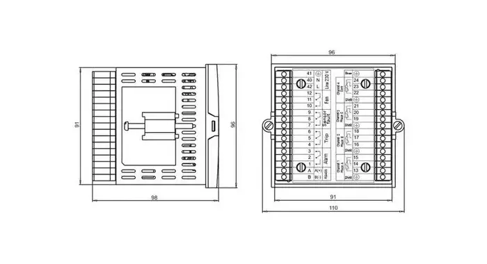
The structure of ТR-100М is made in plastic housing designed for mounting on the front panel of the board (cabinet) or of the device; dimensions of the housing is 96 x 96 x 110 mm. The housing is made of shockproof, self-extinguishing material.

The product has four channels for temperature measurement, and four output load relays. Each load relay is designated for a particular control parameter (like On/Off cooling systems, Alarm, Tripping, Sensor fault).

The temperature transducers (sensors) of the first three channels measure the temperature of each transformer winding; and the fourth one measures temperature of the transformer yoke or ambient temperature.

In case of dangerous temperature rise of the transformer, the product first will enable alarm system and the cooling fans. If the temperature rise continues and the temperature exceeds the limit value, the product will perform emergency shutdown of the transformer.

In case of temperature sensor fault, TR-100M enables the alarm of the transducer fault.
DIGITAL PID TEMPERATURE CONTROLLER TR-101

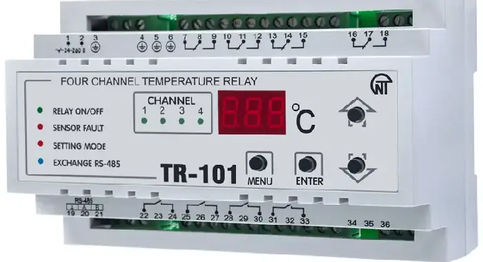
TR-101 digital temperature controller is used to measure and control device temperature via four independent sensors connected in a two or three-wire circuit, with subsequent indication of the temperature on the display. The device can be used in different industrial, utility and agricultural applications.

The device has the following functions:

  • Measuring the temperature on four independent channels using standard sensors
  • Regulating the temperature using the proportionate-integral-differential (PID) principle with an output key unit (relay)
  • Two-level temperature regulation
  • Displaying the currently measured temperature value on the integrated LED digital indicator (scanning)
  • Transmitting the measured temperature values of the controlled sensors to a computer via built-in RS-485 Modbus RTU protocol
  • Discovering line breakdown or faults in connected sensors
  • Digital filtering and correcting of the temperature being measured
  • Programming via the front panel buttons or a PC (free PC software)
  • Saving the settings in case of power outage
  • Protecting the settings against unauthorized changes (password protected)
  • TR-101 can use any voltage between 24 and 260V AC, regardless of the polarity